
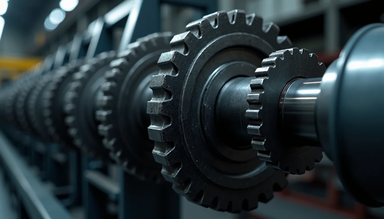
No matter how correctly the chain and sprocket are selected in a drive line, the system will not deliver its expected service life if the connecting element that transfers power to the shaft is wrong. Play forming in the pulley hub, crushing starting in the keyway, or incorrect tightening of a taper bush comes back as vibration, misalignment and premature chain wear.
In this article we cover the power transmission element family — timing pulleys, taper locks, clamping bush pulleys and bushed timing pulleys — together with their selection criteria, installation rules and failure symptoms.
What are power transmission elements?
Power transmission elements are the connecting and fastening components that attach the chain, belt or sprocket carrying motion from the motor to the driven machine onto the shaft. The chain or belt itself performs the power transmission; power transmission elements, in turn, ensure that this component stays on the shaft without slipping, in a centred and removable manner.
In a drive line, the following components typically work together:
- Drive element: chain, timing belt or V-belt
- Transmission element: chain sprocket, timing pulley or V-belt pulley
- Shaft-mounting element: key, taper bush, taper lock or clamping bush
- Bearing arrangement: bearing and bearing housing
The weakest link in this chain is most often the mounting element. An incorrectly selected bush shortens the service life of a correctly calculated chain.
Timing pulley (timing gear)
A timing pulley is a profiled pulley that works together with a toothed belt, its profile matching the belt's teeth. Because it transmits motion without slippage, it is preferred in applications requiring positional precision.
There are three decisive parameters in selection:
- Profile type: Profiles such as HTD, STD, T and AT cannot be used interchangeably. The belt profile and the pulley profile must be exactly the same.
- Pitch: The distance between the belt teeth. Within the HTD family, 3M, 5M, 8M and 14M are common; the number is the pitch expressed in millimetres.
- Number of teeth and width: The number of teeth determines the transmission ratio, while the width determines the torque that can be transmitted.
A common mistake with timing pulleys is using a pulley narrower than the belt width. When the belt edge overhangs the pulley, fibre breakage begins and the belt disintegrates within a few hundred hours.
Taper lock (locking bush)
A taper lock is a clamping element that provides a keyless connection. It generates radial pressure on the shaft as the inner and outer tapered surfaces are drawn together by bolts; motion is transmitted through frictional force.
Its advantages over a keyed connection are as follows:
- No keyway is cut into the shaft, so there is no cross-sectional weakening or stress concentration on the shaft.
- The angular position can be adjusted freely; alignment can be corrected during installation.
- Because it provides a play-free connection, no crushing occurs under reverse-direction or shock loads.
- It has a removable design; it can be taken off during maintenance without damaging the shaft.
The critical point in a taper lock is the tightening torque. The torque value specified by the manufacturer is the direct equivalent of the torque that can be transmitted. A lock tightened below this torque will spin on the shaft, scoring the surface and causing irreparable damage; one tightened above it can crack the hub. Bolts must always be tightened with a torque wrench, in a crosswise sequence, in several stages.
Pulleys with taper bushings
A taper bushing is a standard family of bushings that allows a pulley or sprocket to be fitted onto a shaft quickly. The pulley's hub is machined with a taper bore; the bushing seats into this taper and is locked onto the shaft by tightening the bolts.
The advantage is that the same pulley can be used on different shaft diameters: the bushing is changed while the pulley stays the same. This significantly simplifies stock management. If a plant has five different shaft diameters, one pulley and five bushings are enough, instead of five separate pulleys.
There are three rules for assembly:
- Surfaces must be free of oil. Oil applied to the taper surface lowers the coefficient of friction and causes slipping. The bushing and hub must be fitted clean and dry.
- Bolts are tightened in stages. Fully tightening a single bolt seats the bushing at an angle; tightening must proceed in sequence, with gradually increasing torque.
- Torque is checked after tightening. Torque should be checked again after a short period of operation, as loosening can occur during initial bedding-in.
Bushed timing pulleys
A bushed timing pulley combines the timing belt profile with the taper bushing system. It provides both slip-free motion transmission and quick removal and installation. It is preferred on lines requiring frequent pulley changes, such as those with product changeovers.
The point to note with this group is that as the pulley's tooth count decreases, the range of available bushings narrows. Since the hub volume on low-tooth-count pulleys is limited, a large shaft diameter cannot be accommodated. Shaft diameter and minimum tooth count must be checked together at the design stage.
Signs of failure in transmission components
Problems usually give warning signs before a breakdown occurs. The following signs indicate that a connecting component is faulty:
- Periodic noise and vibration: A knock heard once per revolution points to hub clearance or a centring error.
- Shiny circular mark on the shaft: Indicates that the bushing or lock is spinning on the shaft. The tightening torque is insufficient.
- Crushing in the keyway: This is typical damage caused by reversing loads in a keyed connection; switching to a taper lock should be considered.
- Wear on one edge of the belt: There is axial misalignment between the pulleys.
- Signs of loosening on bolt heads: The tightening torque has dropped and the connection is under fatigue.
These signs also leave marks on the chain side. Misalignment shows up as shiny wear on the side faces of the chain plates. In other words, the source of chain wear is not always the chain itself; it is often a connection or alignment fault. On reading wear marks, chain sprocket dimensions and measurement methods serve as a guide.
Alignment: the lowest-cost improvement
The lowest-cost improvement that can be made on a transmission line is correct alignment. When parallel misalignment and angular misalignment are corrected, chain and belt life increase significantly and bearing loads are reduced.
The sequence of methods that can be applied on site is as follows:
- A straight edge or taut string line is applied to the side faces of the pulleys or sprockets; the two elements must lie in the same plane.
- The parallelism of the shaft axes is checked; measurements are taken from two points.
- The bearing housings are loosened for correction, then tightened to the specified torque values.
- After a short trial run, the temperature difference and noise are checked.
On lines requiring precision, using a laser alignment device gives far more consistent results than the straight-edge method and pays for itself in a short time.
Stock and spare parts planning
When planning spares for transmission components, not just the pulley but the entire connection group should be considered: pulley, bushing, bolt set and, where required, key. Bolts are often overlooked, yet a bolt damaged during disassembly must be replaced with a new one.
On critical lines, a list of bushing dimensions should be kept, with shaft diameter and pulley matches recorded. This list ensures the correct part is sourced on the first attempt at the moment of a breakdown.
At Gurur Makina, we supply standard products in the timing pulley, taper lock, clamping bushed pulley and bushed timing pulley groups; for non-standard sizes, we offer manufacturing to sample. For the full product range and technical documents, power transmission components you can view our page.
Keyed connection or taper lock?
This is the most frequently asked comparison in practice. Both methods have their place; the choice is made according to the load character of the line.
Situations where a keyed connection is suitable
- Drives operating with unidirectional, steady load
- Connections where the position must stay fixed and are not disassembled often
- Low-torque applications where cost is the deciding factor
Situations where taper lock stands out
- Drives that reverse direction or involve shock loads
- Maintenance points requiring frequent disassembly and reassembly
- High-stress shafts where weakening of the shaft cross-section is undesirable
- Synchronised applications where the angular position must be adjusted during assembly
In a keyed connection, reversed-direction load creates impact in the micro-clearance between the key and the keyway. Over time this clearance grows and the keyway becomes crushed. Once crushing begins, replacing the key is no longer a solution; the shaft or hub must be machined. For this reason, on lines that reverse direction, taper lock lowers the total cost of ownership even though its initial investment is higher.
Torque transmission: what is it calculated based on?
When selecting the connecting element, the torque to be transmitted is calculated from motor power and speed. A service factor is then added to this; the factor increases for shock loads and lines that run all day.
The calculated torque value must remain below the transmissible torque value given in the catalogue for the bush or lock to be selected. Selections that stay right at the limit, even if they cause no problems in the first few months, end in surface slippage. In practice, moving up to the next size is far cheaper than the shaft damage caused by that slippage.
For the corresponding calculation on the chain side, the method described in our article titled Machine Chain Selection: Pitch, Breaking Load and Service Factor can be used; the connecting element and the chain must be sized on the basis of the same service factor.
Removal Procedure: Without Damaging the Shaft
Removing taper bushes and locks is just as critical as fitting them. Incorrect removal scores the shaft and cracks the hub.
- The bolts are fully removed. Loosening is not enough; the bolts must be taken out.
- They are fitted into the removal holes. Taper bushes have threaded holes set aside for removal. When bolts are fitted into these holes and tightened in stages, the bush releases itself.
- Do not strike with a hammer. An impact applied to the hub distorts the tapered surface and makes the connection unreliable from then on.
- The surfaces are cleaned. After removal, oxide and burrs are removed from the shaft and hub surfaces; reassembly is carried out on a clean surface.
Frequently asked questions
Should a taper bush be lubricated?
No. Taper surfaces are fitted dry and clean. Grease lowers the coefficient of friction, preventing the required clamping force from developing, and lets the bush rotate on the shaft. A thin oil may be applied to the bolt threads only, if the manufacturer allows it.
If the pulley keeps coming loose, is tightening the bolts further the answer?
No. Exceeding the manufacturer's torque cracks the hub. Repeated loosening shows that the size selected is inadequate, or that the surfaces were assembled dirty. First check surface cleanliness and correct torque; if the problem continues, move up to the next size.
Can the same pulley be used with different shaft diameters?
Yes, with taper-bush pulleys. The pulley stays the same; only the bush is changed. This is the most practical way to reduce stock items. With keyed-hub pulleys, however, the shaft diameter is fixed.
How often should alignment be checked?
At commissioning for a new installation, and every six months thereafter, is sufficient. If one-sided wear appears on the chain or belt, it should be checked straightaway, without waiting for the scheduled interval.
Belt or Chain? Choosing the Transmission Method
The first question to ask when selecting transmission components is whether the line will be driven by belt or by chain. Both methods have their own particular strengths, and this choice determines every subsequent connecting-element decision.
Conditions where chain excels
- High torque, low speed: Chain carries higher torque than a belt of the same cross-section.
- Short centre distance: Chain is advantageous where a high reduction ratio is required within a compact space.
- High temperature and oily environments: Steel chain keeps working under conditions that would degrade a belt.
- Drives where slip is not acceptable: Chain-sprocket engagement is positive; it does not slip.
Conditions where belt excels
- High speed: Belt runs quieter and with less vibration at high speed.
- Long centre distance: Belt is better suited to distances where chain suffers from sag.
- Environments where lubrication is undesirable: Belt requires no lubrication; it is preferred in food and cleanroom applications.
- Need for shock damping: Belt flexibility allows it to partially absorb shock.
Hybrid solutions are also common: lines using a timing belt at the motor output and chain near the working shaft are frequently seen. In this arrangement, the coupling elements on each side must be sized separately.
Commissioning checklist
On a newly installed drive line, or one returning from maintenance, the following steps should be carried out before commissioning:
- Are the shaft and hub surfaces clean, burr-free and dry?
- Has the bush or lock been tightened to the manufacturer's torque, in a cross (diagonal) sequence?
- Are the pulley and sprocket in the same plane; has this been verified with a straightedge or laser?
- Is chain or belt tension within the manufacturer's specified range?
- Have protective guards been fitted?
- Is there any abnormal noise, vibration or heating during no-load running?
- Have torque and tension been rechecked after the first hour of operation?
The last item is the one most often skipped. Yet on taper-lock connections, a torque check carried out after initial bedding-in prevents most cases of early loosening.
The right coupling matters as much as the right chain
A drive line's service life is only as good as its weakest link. Engineering effort spent on chain and sprocket selection counts for little if the shaft coupling element is chosen incorrectly or tightened to insufficient torque.
If your line suffers from recurring pulley loosening, key crushing or premature chain wear, look for the cause not in a single part but in the coupling-alignment-tension triad. Share the dimensions of your current setup and we can determine the right coupling assembly together; for a quote, price request form .